转载:http://www.codeproject.com/KB/WPF/WPF_Text3D.aspx
Download demo - 26.46 KB Download source - 37.19 KB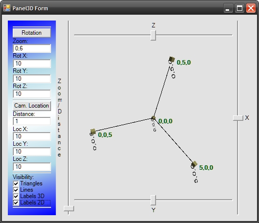
Introduction
Some time ago, I started working on my application that takes the advantages of 3D graphics to display some results. I am .NET developer so I have chosen Windows Presentation Foundation (WPF) as my framework to create 3D graphics. I have to admit that this is powerful library that allows to create 3D graphics quite easy. It is not hard to understand how to create a 3D scene using sets of triangles. What is more, many articles describe how to do it. I encountered some problems when I started adding some text to my 3D scene. I think that this article may help other developers to choose the best way of writing text on a 3D scene.
Background
Let's start, our goal is to add some text labels to the 3D scene. We have at least two approaches:
- 3D label creation
- 2D label creation and overlay it on the scene
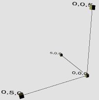
The first approach is based on the creation of a 3D object in the scene (typically it is a rectangle) and writing text on it (it can be achieved using the brush made from text). The sample result is showed in the picture below:
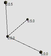
The second approach is based on layers. The bottom layer is Viweport3D and the top layer isCanvas. The top layer is transparent and overlays the Viewport3D. This approach usesTexBlocks that are members of the Canvas but the 2D location depends on the location in 3D space. The picture below presents that approach:
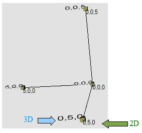
Of course, both approaches have some advantages and disadvantages. The 3D labels based on the first approach are more useful when the text is a part of the scene. The labels based on the second approach are more readable (but the solution is more complex). The picture below shows both approaches:
Using the Code
The sample code draws the coordinate system and some labels on it. The scene could be rotated using the sliders.Checkboxes from the left pane allow to switch on / switch off the visibility of elements of the scene (especially labels 2D and 3D). I do not want to go into detail as to how this application is created. I want to focus on the two approaches mentioned previously.
3D Labels
To illustrate how to create a label in 3D, I am going to describe how to create the function:CreateTextLabel3D. This function is going to be responsible for returning theModelVisual3D object that represents the label in 3D space. Such a function has the following declaration:
/// <summary>
/// Creates a ModelVisual3D containing a text label.
/// </summary>
/// <param name="text">The string to be drawn</param>
/// <param name="textColor">The color of the text.</param>
/// <param name="isDoubleSided">Visible from both sides?</param>
/// <param name="height">Height of the characters</param>
/// <param name="basePoint">The base point of the label</param>
/// <param name="isBasePointCenterPoint">if set to <c>true</c> the base point
/// is center point of the label.</param>
/// <param name="vectorOver">Horizontal direction of the label</param>
/// <param name="vectorUp">Vertical direction of the label</param>
/// <returns>Suitable for adding to your Viewport3D</returns>
/// <remarks>Two vectors: vectorOver and vectorUp are creating the surface
/// on which we are drawing the text. Both those vectors are used for
/// calculation of label size, so it is reasonable that each co-ordinate
/// should be 0 or 1. e.g. [1,1,0] or [1,0,1], etc...</remarks>
public static ModelVisual3D CreateTextLabel3D( string text, Brush textColor,
    bool isDoubleSided, double
    height, Point3D basePoint, bool isBasePointCenterPoint, Vector3D vectorOver,
    Vector3D vectorUp);
How It Works?
- First we need to create a
TextBlockthat allows us to create a label:TextBlock textblock = new TextBlock(new Run(text)); textblock.Foreground = textColor; // setting the text color textblock.FontFamily = new FontFamily("Arial"); // setting the font to be used
- Now we have to create a brush and material that contains the
TextBlockcreated in the previous step:DiffuseMaterial mataterialWithLabel = new DiffuseMaterial(); // Allows the application of a 2-D brush, // like a SolidColorBrush or TileBrush, to a diffusely-lit 3-D model. // we are creating the brush from the TextBlock mataterialWithLabel.Brush = new VisualBrush(textblock);
- Now it is time to create the object in the 3D space that will be covered by the text:
//calculation of text width (assuming that characters are square):
double width = text.Length * height;
// we need to find the four corners
// p0: the lower left corner; p1: the upper left
// p2: the lower right; p3: the upper right
Point3D p0 = basePoint;
// when the base point is the center point we have to set it up in different way
if(isBasePointCenterPoint)
p0 = basePoint - width / 2 * vectorOver - height / 2 * vectorUp;
Point3D p1 = p0 + vectorUp * 1 * height;
Point3D p2 = p0 + vectorOver * width;
Point3D p3 = p0 + vectorUp * 1 * height + vectorOver * width;
// we are going to create object in 3D now:
// this object will be painted using the (text) brush created before
// the object is rectangle made of two triangles (on each side).
MeshGeometry3D mg_RestangleIn3D = new MeshGeometry3D();
mg_RestangleIn3D.Positions = new Point3DCollection();
mg_RestangleIn3D.Positions.Add(p0); // 0
mg_RestangleIn3D.Positions.Add(p1); // 1
mg_RestangleIn3D.Positions.Add(p2); // 2
mg_RestangleIn3D.Positions.Add(p3); // 3
// when we want to see the text on both sides:
if (isDoubleSided)
{
    mg_RestangleIn3D.Positions.Add(p0); // 4
    mg_RestangleIn3D.Positions.Add(p1); // 5
    mg_RestangleIn3D.Positions.Add(p2); // 6
    mg_RestangleIn3D.Positions.Add(p3); // 7
}
mg_RestangleIn3D.TriangleIndices.Add(0);
mg_RestangleIn3D.TriangleIndices.Add(3);
mg_RestangleIn3D.TriangleIndices.Add(1);
mg_RestangleIn3D.TriangleIndices.Add(0);
mg_RestangleIn3D.TriangleIndices.Add(2);
mg_RestangleIn3D.TriangleIndices.Add(3);
// when we want to see the text on both sides:
if (isDoubleSided)
{
    mg_RestangleIn3D.TriangleIndices.Add(4);
    mg_RestangleIn3D.TriangleIndices.Add(5);
    mg_RestangleIn3D.TriangleIndices.Add(7);
    mg_RestangleIn3D.TriangleIndices.Add(4);
    mg_RestangleIn3D.TriangleIndices.Add(7);
    mg_RestangleIn3D.TriangleIndices.Add(6);
}
- We are covering the object created in the previous step using the material created at the beginning:
// texture coordinates must be set to
// stretch the TextBox brush to cover
// the full side of the 3D label.
mg_RestangleIn3D.TextureCoordinates.Add(new Point(0, 1));
mg_RestangleIn3D.TextureCoordinates.Add(new Point(0, 0));
mg_RestangleIn3D.TextureCoordinates.Add(new Point(1, 1));
mg_RestangleIn3D.TextureCoordinates.Add(new Point(1, 0));
// when the label is double sided:
if (isDoubleSided)
{
    mg_RestangleIn3D.TextureCoordinates.Add(new Point(1, 1));
    mg_RestangleIn3D.TextureCoordinates.Add(new Point(1, 0));
    mg_RestangleIn3D.TextureCoordinates.Add(new Point(0, 1));
    mg_RestangleIn3D.TextureCoordinates.Add(new Point(0, 0));
}
- Now it is time to create
ModelVisual3Dthat we want to return:ModelVisual3D result = new ModelVisual3D(); // we are setting the content: // our 3D rectangle object covered with material that is made of label // (TextBox with text) result.Content = new GeometryModel3D(mg_RestangleIn3D, mataterialWithLabel); ; return result;
2D Labels
This solution is much more complicated and it is hard to prepare one function that deals with all tasks.
First of all, we have to create two layers:
-
Viewport3Das the bottom layer -
Canvasas the top layer
The XAML code below presents a sample of two overlaid layers:
<Grid ClipToBounds="True">
<Viewport3D Name="mainViewport" ClipToBounds="True" Grid.Column="0" Grid.Row="0">
<Viewport3D.Camera>
<PerspectiveCamera FarPlaneDistance="100" LookDirection="-11,-10,-9" UpDirection="0,1,0"
    NearPlaneDistance="1" Position="11,10,9" FieldOfView="70" />
</Viewport3D.Camera> <ModelVisual3D> <ModelVisual3D.Content>
<DirectionalLight Color="White" Direction="-2,-3,-1" />
</ModelVisual3D.Content>
</ModelVisual3D>
</Viewport3D> <Canvas Name="mainViewportCanvas" ClipToBounds="True"
	Grid.Column="0" Grid.Row="0">
</Canvas>
</Grid>
The second task is localization of the point from 3D space on our overlaid canvas. To transform the location, we can use the following function:
public static Point Get2DPoint(Point3D p3d, Viewport3D vp)
{
    bool TransformationResultOK;
    Viewport3DVisual vp3Dv = VisualTreeHelper.GetParent(
    vp.Children[0]) as Viewport3DVisual;
    Matrix3D m = MathUtils.TryWorldToViewportTransform
			(vp3Dv, out TransformationResultOK);
    if (!TransformationResultOK) return new Point(0, 0);
    Point3D pb = m.Transform(p3d);
    Point p2d = new Point(pb.X, pb.Y);
    return p2d;
}
Note that this function uses function TryWorldToViewportTransform from 3D Tools package (availablehere): _3DTools.MathUtils.TryWorldToViewportTransform.
The next task is creation and localization of the TextBlock:
UIElement IModelVisual3D.GetUIElement
	(ModelVisual3DFilter FilterSettings, Viewport3D DestinationViewport3D)
{
    if (FilterSettings.Texts2D)
    {
        TextBlock tb = new TextBlock();
        tb.Text = Description;
        Point p2d = Panel3DMath.Get2DPoint(this.Point3D, DestinationViewport3D);
        Canvas.SetTop(tb, p2d.Y);
        Canvas.SetLeft(tb, p2d.X);
        return tb;
    }
    else
        return new UIElement();
}
The last thing is adding the TextBlock (created before) to our canvas.
this.mainViewportCanvas.Children.Add(element.GetUIElement(filter,mainViewport));
Summary
I hope that my two approaches that could be used during creation of text labels for 3D scenes might be interesting for the reader. The Polish version of this article will be available soon onmy blog.