三层交换
学习目的:
-
了解三层交换的意义
-
理解三层交换与路由的异同点
-
掌握vlanif的配置方法
-
掌握valn之间实现通讯的配置方法
-
掌握vlanif之间配置OSPF的方法
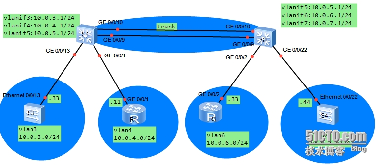
拓扑图:
场景:
你是公司的网络管理员。当前网络中有四个用户。S3、R1、R3与S4模拟为公司用户。分属于不同的vlan,定义S3属于vlan3、R1属于vlan4、R3属于vlan6、S4属于vlan7,实现vlan之间的互通。同时由于S1与S2之间使用三层链路实现互通,所以需要使用路由协议实现路由信息的互相学习。
学习任务
步骤一.S1与S2之间的链路配置成eth-trunk链路
实验之前,需要关闭部分实验设备接口与,避免影响本次试验。
本次实验需要关闭S3的E0/0/1、E0/0/23接口,另外需要关闭S4的E0/0/14接口。关闭这些接口。关闭这些接口后,开始实验配置。
[Huawei]sysname S1
[S1]interface eth-trunk 1
[S1-Eth-Trunk1]q
[S1]interface g0/0/9
[S1-GigabitEthernet0/0/9]eth-trunk 1
[S1-GigabitEthernet0/0/9]interface g0/0/10
[S1-GigabitEthernet0/0/10]eth-trunk 1
Info: This operation may take a fewseconds. Please wait for a moment...done.
[Huawei]sysname S2
[S2]interface eth-trunk 1
[S2-Eth-Trunk1]q
[S2]interface g0/0/9
[S2-GigabitEthernet0/0/9]eth-trunk 1
[S2-GigabitEthernet0/0/9]interface g0/0/10
[S2-GigabitEthernet0/0/10]eth-trunk 1
步骤二.S1、S2配置valn3、4、5、6、7
[S1]vlan batch 3 to 7
[S2]vlan batch 3 to 7
查看vlan的创建情况
[S1]dis vlan
The total number of vlans is : 6
--------------------------------------------------------------------------------
U: Up; D: Down; TG: Tagged; UT: Untagged;
MP: Vlan-mapping; ST: Vlan-stacking;
#: ProtocolTransparent-vlan; *: Management-vlan;
--------------------------------------------------------------------------------
VID Type Ports
--------------------------------------------------------------------------------
1 common UT:GE0/0/1(U) GE0/0/2(D) GE0/0/3(D) GE0/0/4(D)
GE0/0/5(D) GE0/0/6(D) GE0/0/7(D) GE0/0/8(D)
GE0/0/11(D) GE0/0/12(D) GE0/0/13(U) GE0/0/14(D)
GE0/0/15(D) GE0/0/16(D) GE0/0/17(D) GE0/0/18(D)
GE0/0/19(D) GE0/0/20(D) GE0/0/21(D) GE0/0/22(D)
GE0/0/23(D) GE0/0/24(D) Eth-Trunk1(U)
3 common
4 common
5 common
6 common
7 common
VID Status Property MAC-LRN Statistics Description
--------------------------------------------------------------------------------
1 enable default enable disable VLAN 0001
3 enable default enable disable VLAN 0003
4 enable default enable disable VLAN 0004
5 enable default enable disable VLAN 0005
6 enable default enable disable VLAN 0006
7 enable default enable disable VLAN 0007
[S2]dis vlan
The total number of vlans is : 6
--------------------------------------------------------------------------------
U: Up; D: Down; TG: Tagged; UT: Untagged;
MP: Vlan-mapping; ST: Vlan-stacking;
#: ProtocolTransparent-vlan; *: Management-vlan;
--------------------------------------------------------------------------------
VID Type Ports
--------------------------------------------------------------------------------
1 common UT:GE0/0/1(D) GE0/0/2(U) GE0/0/3(D) GE0/0/4(D)
GE0/0/5(D) GE0/0/6(D) GE0/0/7(D) GE0/0/8(D)
GE0/0/11(D) GE0/0/12(D) GE0/0/13(D) GE0/0/14(D)
GE0/0/15(D) GE0/0/16(D) GE0/0/17(D) GE0/0/18(D)
GE0/0/19(D) GE0/0/20(D) GE0/0/21(D) GE0/0/22(U)
GE0/0/23(D) GE0/0/24(D) Eth-Trunk1(U)
3 common
4 common
5 common
6 common
7 common
VID Status Property MAC-LRN Statistics Description
--------------------------------------------------------------------------------
1 enable default enable disable VLAN 0001
3 enable default enable disable VLAN 0003
4 enable default enable disable VLAN 0004
5 enable default enable disable VLAN 0005
6 enable default enable disable VLAN 0006
7 enable default enable disable VLAN 0007
步骤三.S1与S2之间的Eth-trunk链路配置为Access链路,属于vlan5
配置vlan与接口之间的对应关系。S1与S2之间的eth-trunk属于vlan5,S1的G0/0/1属于vlan4、G0/0/13属于vlan3;S2的G0/0/2属于vlan6、G0/0/22属于vlan7.
[S1]interface eth-trunk 1
[S1-Eth-Trunk1]port link-type access
[S1-Eth-Trunk1]port default vlan 5
[S1-Eth-Trunk1]interface g0/0/1
[S1-GigabitEthernet0/0/1]port link-typeaccess
[S1-GigabitEthernet0/0/1]port default vlan4
[S1-GigabitEthernet0/0/1]interface g0/0/13
[S1-GigabitEthernet0/0/13]port link-typeaccess
[S1-GigabitEthernet0/0/13]port default vlan3
[S2]interface eth-trunk 1
[S2-Eth-Trunk1]port link-type access
[S2-Eth-Trunk1]port default vlan 5
[S2-Eth-Trunk1]interface g0/0/2
[S2-GigabitEthernet0/0/2]port link-typeaccess
[S2-GigabitEthernet0/0/2]port default vlan6
[S2-GigabitEthernet0/0/2]interface g0/0/22
[S2-GigabitEthernet0/0/22]port link-typeaccess
[S2-GigabitEthernet0/0/22]port default vlan7
步骤四.S1与S2为相应的vlan配置网关IP地址。
S1为vlan3、4、5提供网关服务、S2为vlan5、6、7提供网关服务。
[S1]interface vlanif 3
[S1-Vlanif3]
Jul 2 2014 18:51:13-08:00 S1 %%01IFNET/4/IF_STATE(l)[1]:Interface Vlanif3has tu
rned into UP state.
[S1-Vlanif3]ip add 10.0.3.1 24
[S1-Vlanif3]interface vlan 4
[S1-Vlanif4]ip add 10.0.4.1 24
[S1-Vlanif4]interface vlanif 5
[S1-Vlanif5]ip add 10.0.5.1 24
[S2]interface vlanif 5
[S2-Vlanif5]ip add 10.0.5.2 24
[S2-Vlanif5]interface vlan 6
[S2-Vlanif6]ip add 10.0.6.1 24
[S2-Vlanif6]interface vlanif 7
[S2-Vlanif7]ip add 10.0.7.1 24
步骤五.S3、R1、R3、S4配置相应的IP地址,病配置缺省路由
[Huawei]sysname S3
[S3]interface vlanif 1
[S3-Vlanif1]ip add 10.0.3.33 24
[S3]q
[S3]ip route-static 0.0.0.0 0.0.0.010.0.3.1
注:由于交换机的物理接口无法配置IP地址,所以我们只能通过vlanif接口实现。虽然S3逻辑上属于S1上定义的vlan3,但是S3的E0/0/13接口在S3上属于vlan1,所以在S3上我们给Vlanif1配置Ip地址,才能将S3模拟成一台连接到S1的主机,并属于vlan3.S4交换机的配置思路与这里一样。
[Huawei]sysname R1
[R1]interface g0/0/1
[R1-GigabitEthernet0/0/1]ip add 10.0.4.1124
[R1-GigabitEthernet0/0/1]q
[R1]ip route-static 0.0.0.0 0.0.0.010.0.4.1
[r3]sysname R3
[R3]interface g0/0/2
[R3-GigabitEthernet0/0/2]ip add 10.0.6.3324
[R3-GigabitEthernet0/0/2]q
[R3]ip route-static 0.0.0.0 0.0.0.010.0.6.1
[Huawei]sysname S4
[S4]interface vlanif 1
[S4-Vlanif1]ip add 10.0.7.44 24
[S4-Vlanif1]q
[S4]ip route-static 0.0.0.0 0.0.0.010.0.7.1
步骤六.测试vlan3与vlan4之间的连通性
在R1上测试与S3的连通性
<R1>ping10.0.3.33
PING 10.0.3.33: 56 data bytes, press CTRL_C to break
Reply from 10.0.3.33: bytes=56 Sequence=1ttl=254 time=40 ms
Reply from 10.0.3.33: bytes=56 Sequence=2ttl=254 time=40 ms
Reply from 10.0.3.33: bytes=56 Sequence=3ttl=254 time=60 ms
Reply from 10.0.3.33: bytes=56 Sequence=4ttl=254 time=50 ms
Reply from 10.0.3.33: bytes=56 Sequence=5ttl=254 time=70 ms
--- 10.0.3.33 ping statistics ---
5 packet(s) transmitted
5 packet(s) received
0.00% packet loss
round-trip min/avg/max = 40/52/70 ms
在R1上测试与R3的连通性,如下
<R1>ping10.0.6.33
PING 10.0.6.33: 56 data bytes, press CTRL_C to break
Request time out
Request time out
Request time out
Request time out
Request time out
--- 10.0.6.33 ping statistics ---
5 packet(s) transmitted
0 packet(s) received
100.00% packet loss
R1与R3之间不能通信。可依照以下检查思路进行故障排除。
<R1>tracert10.0.6.33
traceroute to 10.0.6.33(10.0.6.33), max hops: 30 ,packet length: 40,press CTRL_C tobreak
1 10.0.4.1 30 ms 10 ms 20 ms
2 10.0.4.1 30 ms !N 10 ms !N 20 ms !N
如上显示,R1已经把目标地址10.0.6.33的数据报发送出去了。但是10.0.4.1(即网关)回应网络不可达。
所以可以到网关S1上查看是否因为路由原因而不可达。
[S1]dis iprouting-table
Route Flags: R -relay, D - download to fib
------------------------------------------------------------------------------
Routing Tables:Public
Destinations : 8 Routes : 8
Destination/Mask Proto Pre Cost Flags NextHop Interface
10.0.3.0/24 Direct 0 0 D 10.0.3.1 Vlanif3
10.0.3.1/32 Direct 0 0 D 127.0.0.1 Vlanif3
10.0.4.0/24 Direct 0 0 D 10.0.4.1 Vlanif4
10.0.4.1/32 Direct 0 0 D 127.0.0.1 Vlanif4
10.0.5.0/24 Direct 0 0 D 10.0.5.1 Vlanif5
10.0.5.1/32 Direct 0 0 D 127.0.0.1 Vlanif5
127.0.0.0/8 Direct 0 0 D 127.0.0.1 InLoopBack0
127.0.0.1/32 Direct 0 0 D 127.0.0.1 InLoopBack0
[S1] Userinterface con0 is available
这里可以看到S1缺少到达10.0.6.0网段路由。
原因是这个网段与S1没有直连,未配置静态路由或者动态路由协议。
步骤七.S1与S2之前启用路由协议OSPF
[S1]ospf 1
[S1-ospf-1]area0
[S1-ospf-1-area-0.0.0.0]network10.0.0.0 0.255.255.255
[S2]ospf 1
[S2-ospf-1]area0
[S2-ospf-1-area-0.0.0.0]network10.0.0.0 0.255.255.255
配置完成后,稍等片刻,待S1与S2的OSPF协议相互交换路由信息后。查看S1的路由表。
[S1]dis iprouting-table
Route Flags: R -relay, D - download to fib
------------------------------------------------------------------------------
Routing Tables:Public
Destinations : 10 Routes : 10
Destination/Mask Proto Pre Cost Flags NextHop Interface
10.0.3.0/24 Direct 0 0 D 10.0.3.1 Vlanif3
10.0.3.1/32 Direct 0 0 D 127.0.0.1 Vlanif3
10.0.4.0/24 Direct 0 0 D 10.0.4.1 Vlanif4
10.0.4.1/32 Direct 0 0 D 127.0.0.1 Vlanif4
10.0.5.0/24 Direct 0 0 D 10.0.5.1 Vlanif5
10.0.5.1/32 Direct 0 0 D 127.0.0.1 Vlanif5
10.0.6.0/24 OSPF 10 2 D 10.0.5.2 Vlanif5
10.0.7.0/24 OSPF 10 2 D 10.0.5.2 Vlanif5
127.0.0.0/8 Direct 0 0 D 127.0.0.1 InLoopBack0
127.0.0.1/32 Direct 0 0 D 127.0.0.1 InLoopBack0
此时S1通过OSPF协议学到了两条路由信息。
测试R1与R3之间的连通性。
<R1>ping10.0.6.33
PING 10.0.6.33: 56 data bytes, press CTRL_C to break
Reply from 10.0.6.33: bytes=56 Sequence=1ttl=253 time=70 ms
Replyfrom 10.0.6.33: bytes=56 Sequence=2 ttl=253 time=60 ms
Reply from 10.0.6.33: bytes=56 Sequence=3ttl=253 time=60 ms
Reply from 10.0.6.33: bytes=56 Sequence=4ttl=253 time=70 ms
Reply from 10.0.6.33: bytes=56 Sequence=5ttl=253 time=60 ms
--- 10.0.6.33 ping statistics ---
5 packet(s) transmitted
5 packet(s) received
0.00% packet loss
round-trip min/avg/max = 60/64/70 ms
<R1>ping10.0.7.44
PING 10.0.7.44: 56 data bytes, press CTRL_C to break
Reply from 10.0.7.44: bytes=56 Sequence=1ttl=253 time=80 ms
Reply from 10.0.7.44: bytes=56 Sequence=2ttl=253 time=50 ms
Reply from 10.0.7.44: bytes=56 Sequence=3ttl=253 time=70 ms
Reply from 10.0.7.44: bytes=56 Sequence=4ttl=253 time=90 ms
Reply from 10.0.7.44: bytes=56 Sequence=5ttl=253 time=60 ms
--- 10.0.7.44 ping statistics ---
5 packet(s) transmitted
5 packet(s) received
0.00% packet loss
round-trip min/avg/max = 50/70/90 ms

